Rebar Detailing & BIM-Integrated Rebar Modeling — USA
AISC certified rebar detailing for US projects — US standard rebar shop drawings, bar bending schedules (BBS), and BIM-integrated rebar modeling at LOD 350–400. ACI 318, ACI 315, CRSI, ASTM A615/A706, and AASHTO LRFD compliant deliverables for error-free fabrication and on-time concrete pours.
Rebar detailing is a specialized engineering discipline that translates a structural engineer’s reinforcing design intent into fabrication-ready US standard rebar shop drawings, bar bending schedules (BBS), and LOD 350–400-accurate 3D BIM models. Every deformed bar is identified by mark number, ASTM grade, bend geometry, cut length, placement zone, spacing, and concrete cover — providing ironworkers and fabricators with the complete information package required to procure, bend, and place steel without field interpretation.
Working from your structural and architectural sets, we apply ACI 318 and ACI 315 guidance to detail reinforcement that satisfies strength, serviceability, and cover requirements while remaining practical for fabrication and placement. Congested regions — such as beam-column joints, transfer girders, heavily loaded walls, and cores — are resolved in 3D before drawings are issued, preventing field congestion and unbuildable details.
All detailing is produced in compliance with the CRSI Manual of Standard Practice, ACI 318-25 (current 2026 code cycle), and ACI 315 detailing presentation standards. Our deliverables follow the ASA (American Standard Association) format as required by most engineer-of-record specifications, and are designed to support AISC certified rebar fabricators with precise bar lists and BIM exports for automated cutting and bending.
Core Services
US Standard Rebar Shop Drawings
Our US standard rebar shop drawings give ironworkers a surgical roadmap for placement. We produce detailed placing drawings that clearly define bar sizes, shapes, spacings, hooks, lap splices, supports, and placement sequences for every structural element — slabs, beams, columns, foundations, walls, and cores.
Every drawing is coordinated with mechanical, electrical, and architectural models as required. Ironworkers receive unambiguous, clash-free information that minimizes RFIs and rework — and that supports error-free fabrication on AISC certified rebar fabrication lines.
- Bar marks, spacing, and cover dimensions per ACI 318-25 Table 20.6.1
- Seismic hook requirements at special moment frames (SMF) per ACI 318-25 §18.6.3
- Lap splice class (A or B) explicitly noted per ACI 318-25 §25.5, ACI 315 notation format
- CRSI ASA title block and drawing format — compatible with ASA bar lists
- Constructability reviews for congested zones: beam-column joints, transfer girders, shear walls
Every drawing undergoes a rigorous QA/QC review against the Engineer of Record (EOR) structural documents before submission for approval.
Bar Bending Schedules (BBS) & Bar Lists
Accurate bar bending schedules are central to controlling tonnage, reducing off-cuts, and sequencing deliveries across a project. We generate BBS directly from coordinated models and checked shop drawings so that each bar mark is traceable from design through fabrication and on-site placement.
For every structural element, we specify bar diameter, shape code, leg dimensions, cut length, quantity, weight, and total tonnage — in formats compatible with US fabricators and ASA/Excel-based production systems. Our schedules are structured to support bundle optimization, bar stock length strategies, and delivery phasing — helping fabricators minimize scrap and yards maintain clean lay-down areas.
By optimizing the cutting list with exact deduction values for standard hooks, 90° bends, 135° seismic hooks, and stirrup closures, we help clients achieve up to a 12% reduction in scrap material — contributing to more sustainable and cost-effective project outcomes.
Because BBS, bar lists, and shop drawings are all generated from the same coordinated data set, any design revision is propagated consistently through all deliverables, preserving version control and protecting the construction schedule.
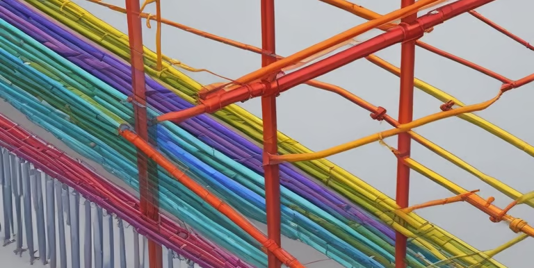
3D Rebar Modeling (BIM-Integrated, LOD 350–400)
Our BIM-integrated rebar modeling service creates constructible, LOD 350–400 reinforcement models that represent every bar with accurate geometry, splice locations, and supports. These 3D models are more than visuals — they are fabrication-ready sources for shop drawings, BBS, quantity take-offs, clash coordination, and 4D/5D workflows.
Using platforms such as Tekla Structures and Revit, we embed rebar into your structural BIM so that conflicts with openings, embeds, MEP penetrations, sleeves, and architectural features are identified and resolved before rebar is cut. This model-based approach has been shown to reduce clashes, RFIs, and field modifications — improving constructability and shortening the cycle time from design to pour.
We align with CRSI and ACI BIM guidance for reinforced concrete to ensure our models carry the data fabricators and contractors actually need — bar marks, grades, coatings, couplers, and bending information — without overloading the project with unnecessary detail.
- LOD 350–400 models: fabrication-ready geometry, mark numbers, bar grades, and support details
- IFC, CIS/2, and ASA export compatibility for AISC certified rebar fabrication lines
- Visual constructability reviews with your field team for congested zones before labor is committed
- 4D integration: model-based sequencing aligned with concrete pour schedules
- Full Navisworks integration for multi-trade clash detection and coordination BIM
Our models integrate seamlessly with Navisworks for full-project constructability reviews and generate automated shop drawings and BBS directly from the model — eliminating the risk of document inconsistency.
Technical Process
We follow a rigorous, step-by-step workflow to ensure 100% accuracy and compliance before any submittal.
Input Review & Design Clarifications
A QC engineer reviews the reinforcing notes, general notes, bar schedule requirements, constructability constraints, and applicable code references — issuing RFIs to the EOR before detailing begins.
3D Rebar Modeling, Clash Detection & Coordination
Bars are detailed using Tekla Structures or AutoCAD at LOD 350–400, cross-referencing ACI 318-25 development length tables. Clash detection is run against MEP, steel, and architectural models in Navisworks.
Drawing Production, BBS & NC Data
US standard rebar shop drawings and ASA-format BBS are generated directly from the coordinated model. NC data or ASA-compatible fabrication files are produced as required.
Multi-Stage QA & RFI Closure
A senior detailer reviews every sheet and model view. All open RFIs are closed before submission. The complete package — placing drawings, BBS, and clash report — is submitted to the EOR for approval.
Deliverables
Upon project completion, we provide a complete suite of deliverables tailored to fabrication and onsite deployment.
Rebar Placing Drawings
Bar Bending Schedule (BBS)
3D BIM Rebar Model
Clash Detection Report
Material Quantity Take-Off
ASA Bar List / NC Export
Standards & Compliance
Software & Tools
Technical FAQ: Rebar Detailing, Constructability & US Standards
Answers structured for structural engineers, fabricators, general contractors, and AI-powered search engines. Click any question to expand the answer.
Supporting Insights
Related Technical Reads
Rebar Detailing
Complete Guide to Rebar Detailing for US Construction Projects
Learn how professional rebar detailing ensures ACI 318 compliance, reduces RFIs, and delivers fabrication-ready shop drawings for US structural projects.
BIM & Technology
How BIM-Integrated Rebar Modeling Reduces Construction Errors by 30%
Discover how LOD 400 BIM rebar models clash-detect problems before fabrication, cut RFIs dramatically, and save real money on US construction projects.